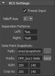
Here, the settings global to the bcs node are configured.

Click an item on the image to jump to its description.
Freeze Input
If this check box is activated, changes to the input geometry are ignored.
Warning NEVER touch vertices of the base geometry while Freeze Input is turned on. If you do, you won’t see the changes you make with the vertices. When reloading the scene (or changing the Freeze Input state), chances are you get shocked by what you see, since it will not be what you saw the last time you worked on the scene.
There could be a second case where the Freeze Input option does something unexpected. If the object has changing history before the bcs node. In this case, the changes of the history will be ignored and only visible after a reload. The solution is to not have changing (animated) history before the bcs. Skinning and other history should be added after the bcs. |
Warning Freeze Input should always be checked. Uncheck it only when you know what you’re doing. Unchecking will lead to severe performance decreases even when you just want to move the deformed object or one of the dataPoint geometry objects. |
Falloff Axis
This is used for automatically creating the unilateral sub-dataPoints. These are created using a falloff you can specify for each bilateral dataPoint. The falloff axis defines the axis across which the dataPoint should be split. If your object faces in z-direction, set the axis to X. When your object faces in x-direction, use the Z axis as the falloff axis.
Separation Patterns
Specify the separation patterns for creating the left and right weight value names of bilateral weights.
Data Point Snapshots
Specify the settings for the Data Point Snapshots feature. Path is the directory on the hard drive where the jpeg images are stored. You may specify a different directory for different BCS nodes in the same scene or use the same directory for all nodes, even from different scenes.
All images of one particular BCS node start with the Prefix string. They differ only by an appended number, which is the ID of the corresponding dataPoint.
W/H specifies the size in which the images are stored. The image is shrunk with fixed aspect ratio until no dimension is bigger than specified.
Crop to does not affect the stored images. It only controls which part of the images is shown in the GUI.